SL16X5
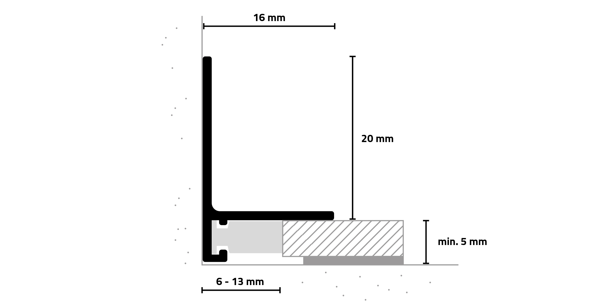
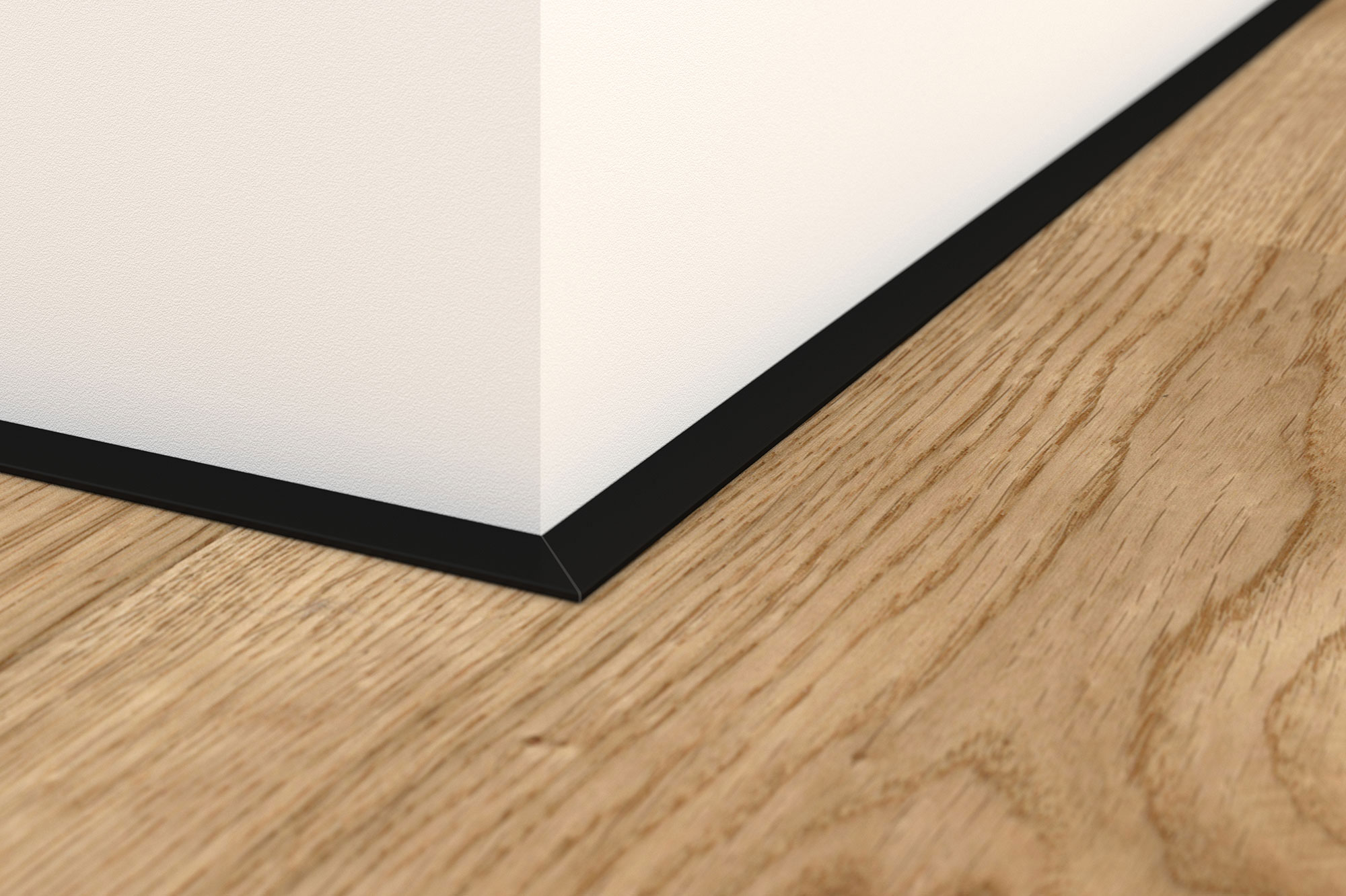
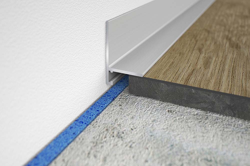
The minileiste SL16X5 skirting profile creates a discreet and innovative finish from the floor covering to the wall, window (frame) or stair tread – ideal for areas where connection and expansion joints are required by construction standards.
Suitable for bonded floor coverings such as parquet, tiles and levelled floors with a floor thickness from 5 mm and a connection joint between 6 and 13 mm.
6 high-quality standard surfaces
SILVER
Silk matt EV1
TITANIUM
Silk matt C31
BLACK
Silk matt C35
WHITE
Fine structure RAL9016
GOLD
Silk matt EV3
ANTHRACITE
Fine structure RAL7016
Tool-free, quick and easy
Our SL16X5 skirting profile can be installed easily, without tools and without visible fixing points: No drilling, no screws, no hammering, no mess, no noise, no hassle. Irregularities in the masonry can be easily levelled out by simply attaching additional mounting clips if required.
Simple installation in just 8 steps
Step 1
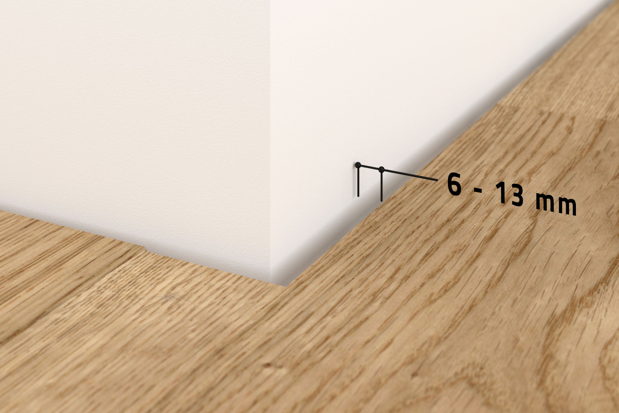
The width of the connection joint should be between 6 and 13 mm depending on the profile system used (see data sheets). The thickness of the floor covering must also be taken into account. Our X5 systems can be used from a minimum floor covering thickness of 5 mm.
Step 2
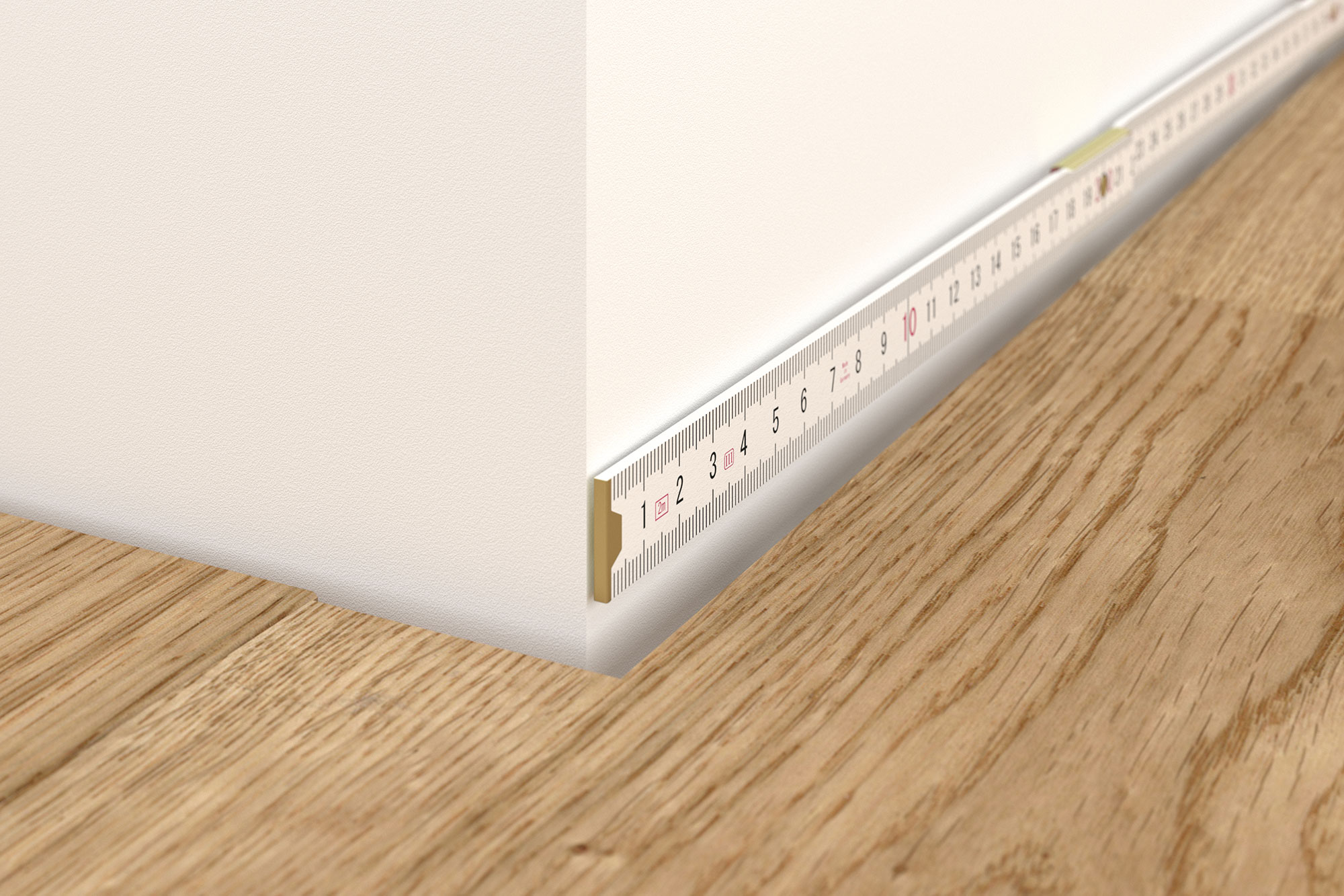
The dimensions for the profile cuts are taken from the wall surfaces. Miter cuts for inside and outside corners are taken into account.
Step 3
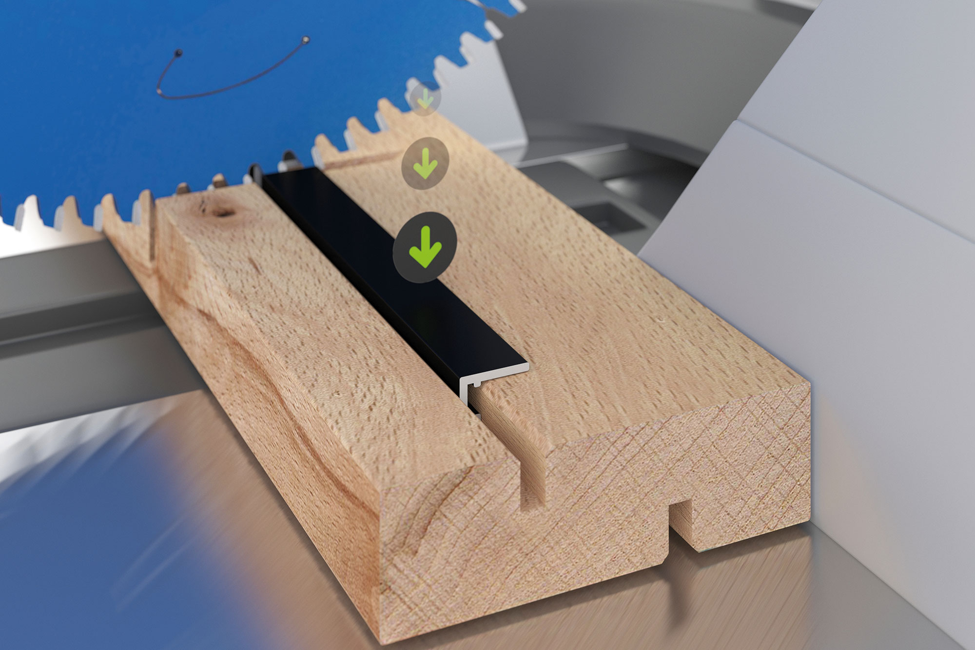
The profiles are cut to size. The miter cut for the inside or outside corner is made in one operation. The profile is pressed securely onto a wooden support and positioned in the saw so that it is cut. The cutting direction of the saw presses the profile against the wood support during the cutting process.
Step 5
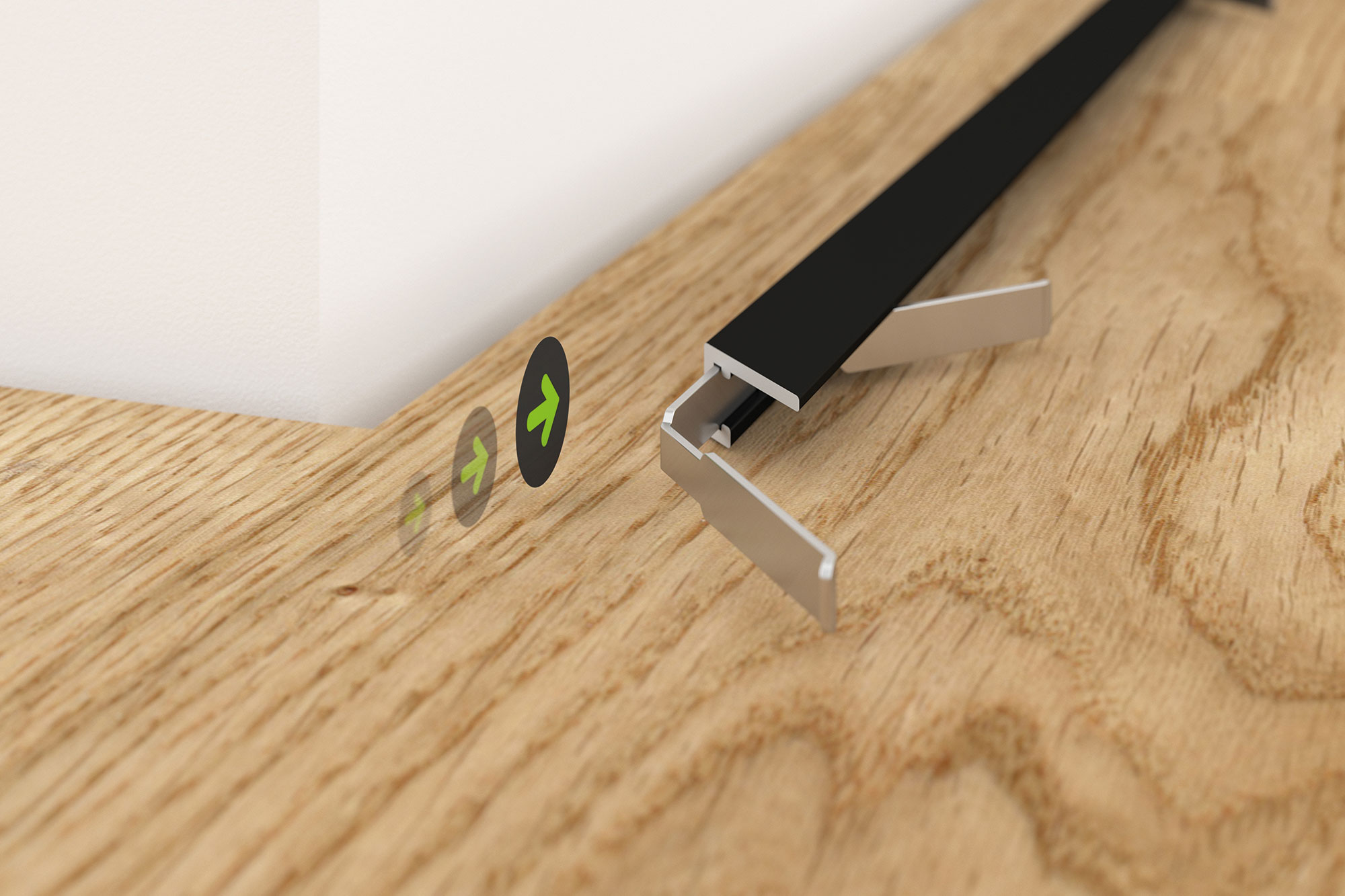
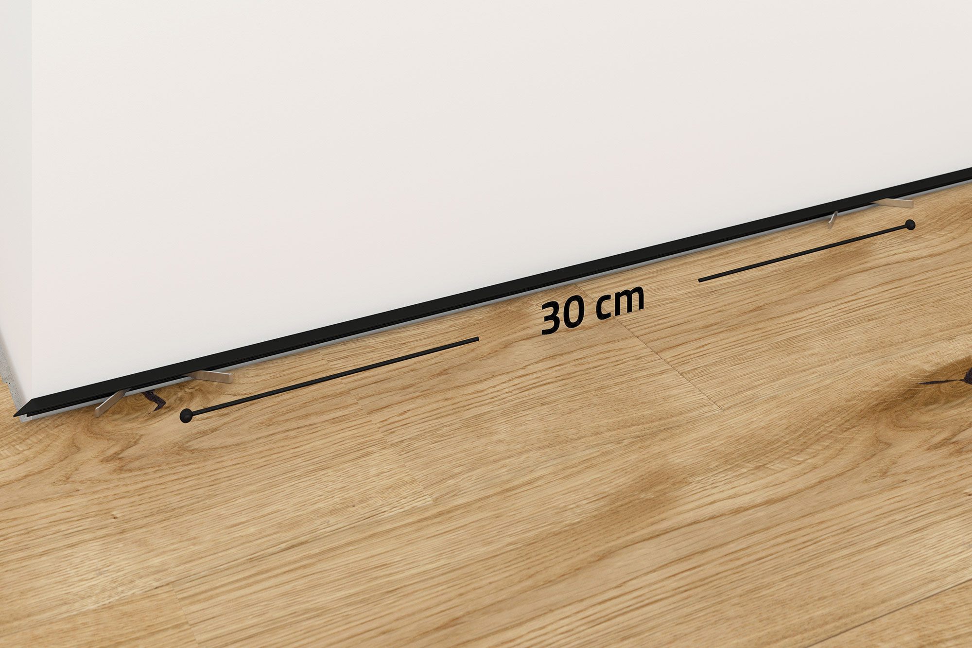
The mounting clips should be pushed into the end strip at a distance of about 30 to 60 cm from one another. Depending on the unevenness in the masonry, individual mounting clips can be installed at closer intervals so that the end strip is flush with the masonry.
Step 6
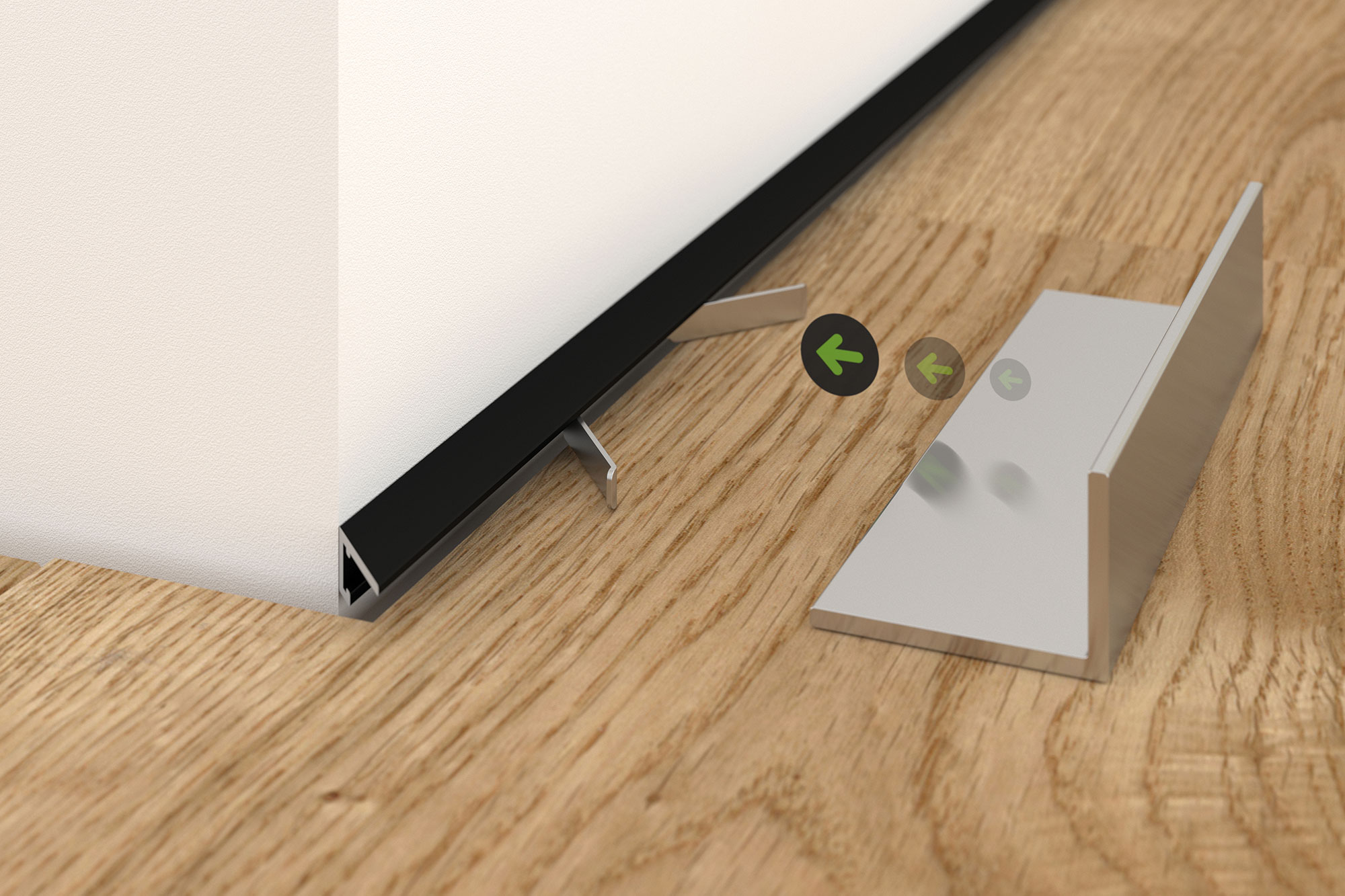
The end strip with the inserted mounting clips is now brought into the mounting position on the wall surface. With the mounting aid, the mounting clips are carefully spread apart by pressing the mounting clips towards the wall with the mounting aid.
Step 7
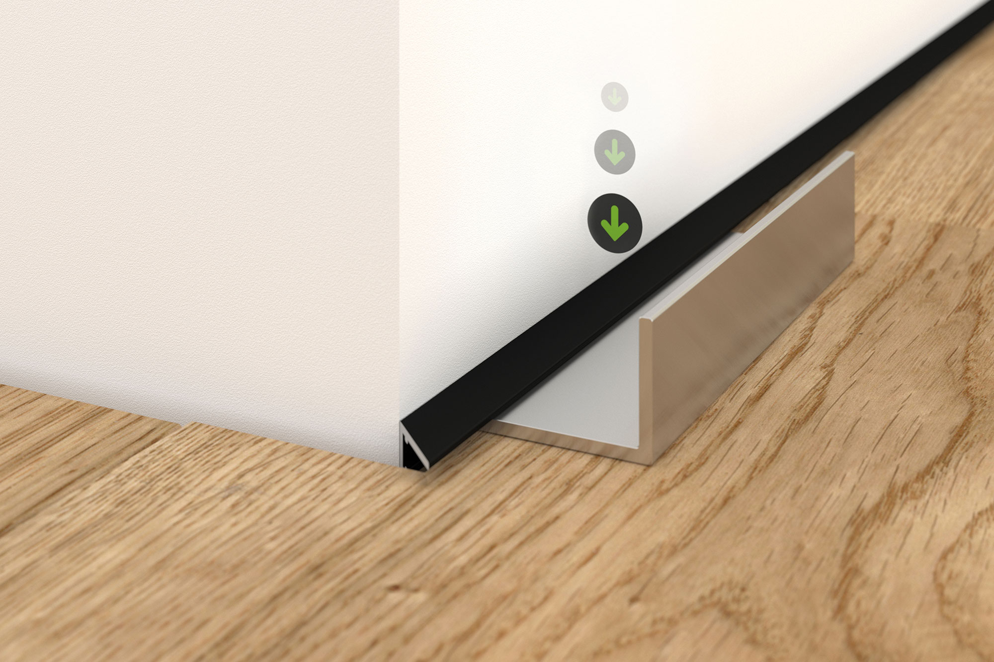
As soon as the clamping process is complete, the end strip is pressed down and the assembly aid removed. Now the tensioning and assembly process is repeated until all assembly clips of an end strip are tensioned and sunk. The end strip can be removed from the connection joint at any time for any corrections.
